

For modern electronics operating on the 2.4 GHz ISM band—which includes Wi-Fi, Bluetooth (BLE), and Zigbee—the surface-mount (SMD) ceramic antenna is often the most practical solution. Unlike bulky external antennas or complicated PCB trace antennas, a ceramic chip antenna delivers high performance in a footprint that can be as small as a grain of rice.
But how do you choose the right one, and does the protocol matter? Let’s break down what makes the best Wi-Fi, Bluetooth, and Zigbee ceramic antennas, and how to implement them successfully in your next board spin.
Do You Need Different Antennas for Wi-Fi, Bluetooth, and Zigbee?
This is the most common question from junior buyers and designers. The short answer is no.
Wi-Fi (802.11 b/g/n), Bluetooth, and Zigbee all operate within the 2.4 GHz to 2.5 GHz ISM (Industrial, Scientific, and Medical) band. Because the physical radio frequency is the same, a high-quality 2.4GHz ceramic antenna will work perfectly for all three protocols.
You don't need a "Bluetooth specific" or "Zigbee specific" antenna. Instead, what you are looking for is a 2.4GHz ceramic chip antenna with excellent bandwidth, high efficiency, and a footprint that matches your PCB constraints.
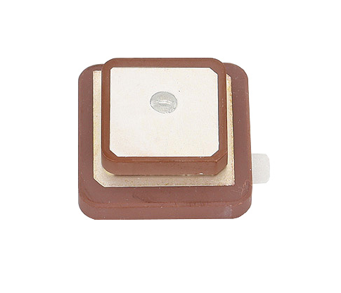
Why Choose a Ceramic Chip Antenna?
Engineers typically choose between trace antennas (drawn directly onto the copper of the PCB), flexible printed circuits (FPC), and ceramic antennas. Here is why ceramic often wins for compact IoT devices:
-
Extreme Miniaturization: Standard sizes like 3216 (3.2 x 1.6 mm) or even smaller allow you to fit RF capabilities into smartwatches, ear-buds, and USB dongles.
-
Less Affected by Proximity: PCB trace antennas easily become detuned if the user's hand touches the plastic enclosure or if a battery is placed nearby. Ceramic antennas use a high dielectric constant material, which contains the RF field more tightly and makes them less sensitive to environmental interference.
-
Manufacturing Consistency: Every ceramic chip is manufactured to exact tolerances. PCB trace antennas can suffer from performance variations if the board house changes the FR4 material thickness or copper plating.
Key Specs to Look For
When evaluating datasheets to find the best ceramic antenna for your project, ignore the marketing fluff and look directly at these RF parameters:
-
Frequency Range: Must cover 2400 MHz to 2500 MHz.
-
VSWR (Voltage Standing Wave Ratio): Look for a VSWR of
< 2.0. This indicates that most of the power from your RF module is successfully being transmitted into the air, rather than bouncing back and creating heat. -
Peak Gain: Typically between
0.5 dBi to 3.0 dBi. Higher gain isn't always better; for a wearable device, you want an omnidirectional radiation pattern rather than a focused beam. -
Efficiency: A good ceramic antenna should offer over 60% to 70% efficiency. High efficiency directly translates to better battery life for BLE and Zigbee sensors.
Design Tips: Making Your Antenna Actually Work
Buying the "best" antenna is only 20% of the battle. The other 80% is how you place it on your PCB. Even a premium component will perform terribly if the layout is flawed.
-
Respect the Keep-Out Zone: Ceramic antennas require a "clearance area" directly underneath and around them where no copper (ground plane, traces, or vias) is allowed. The datasheet will specify the exact dimensions of this clearance. Do not shrink it.
-
Edge or Corner Placement: Mount the antenna on the edge or, ideally, the corner of your PCB. Placing an antenna in the dead center of a board will trap the signal.
-
Include a Pi-Matching Network: Always design a Pi-network (a series footprint with two shunt footprints to ground) between your RF chip and the antenna. Even if the antenna is tuned to 50 ohms out of the box, the specific plastic housing of your product will detune it slightly. The matching network allows you to fine-tune the impedance later without redesigning the whole board.